Home
Company
About us
mission and people
Contact us
let’s connect
Join our team
powering photonics
Products
All products
browse our catalogue
Control modules
explore the family
Wiring
boards and cabling
Motion control
motors and actuators
Support
FAQs
answers to frequently asked questions
Downloads
data sheets, manuals, and more
Python API
interface software
Email us
we’re here for you
Future
Account
Home
/
Blog
In Blog
Application Notes
,
Software
Getting started with the Python module
By
Josh
•
Aug 9
News
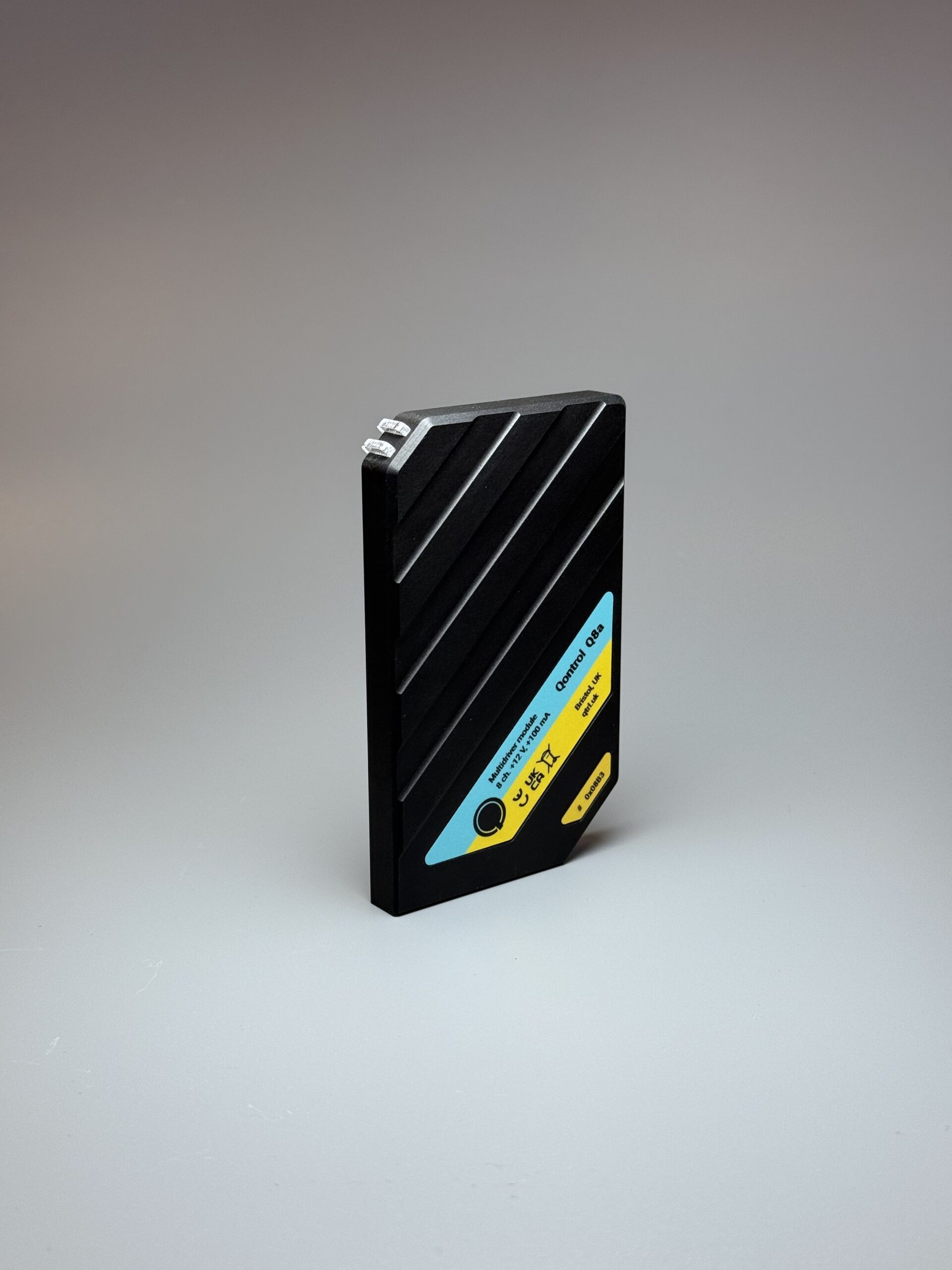
Q8a photonics driver launch
By
Marija Radulovic
•
Mar 26
Application Notes
,
Software
,
Support
How to speed up serial communication on Windows
By
Charity Carter
•
Jan 18
News
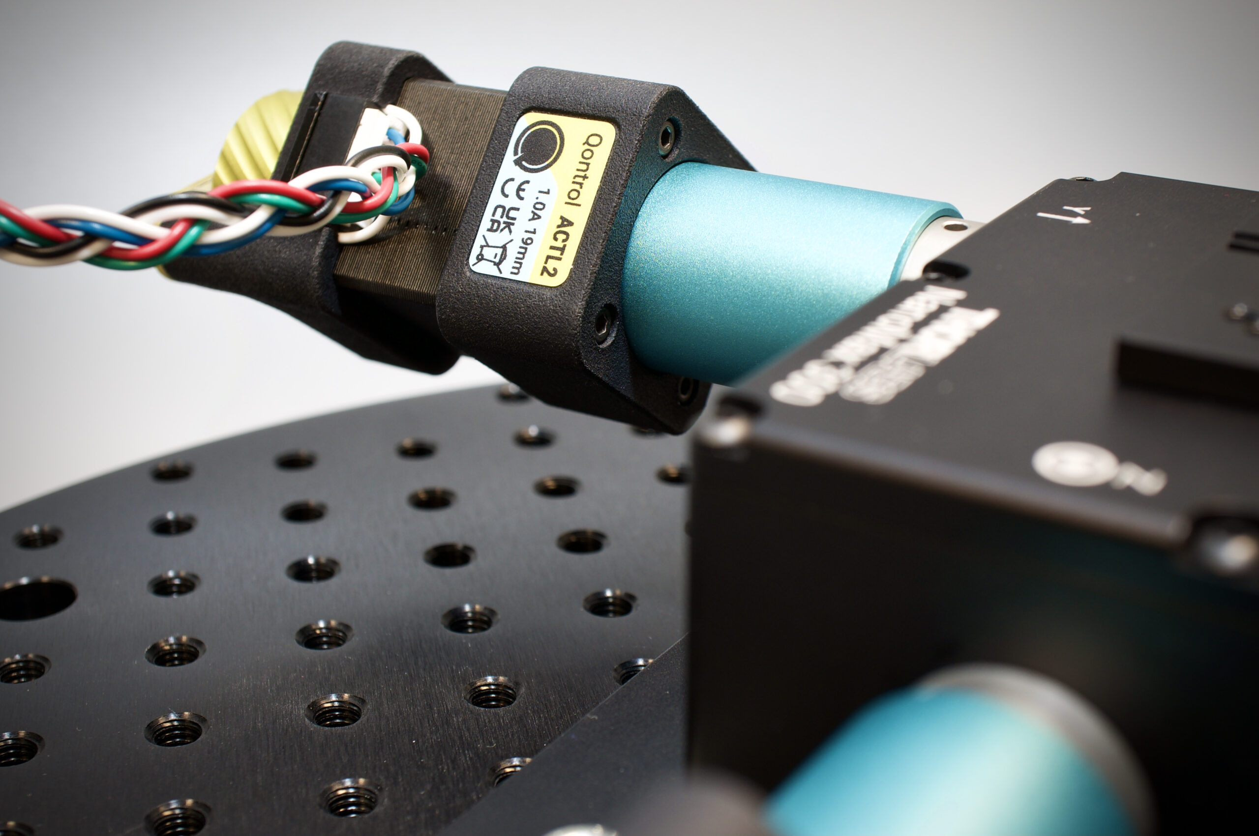
Motion Qontrol is Here
By
Josh
•
Apr 8
Support
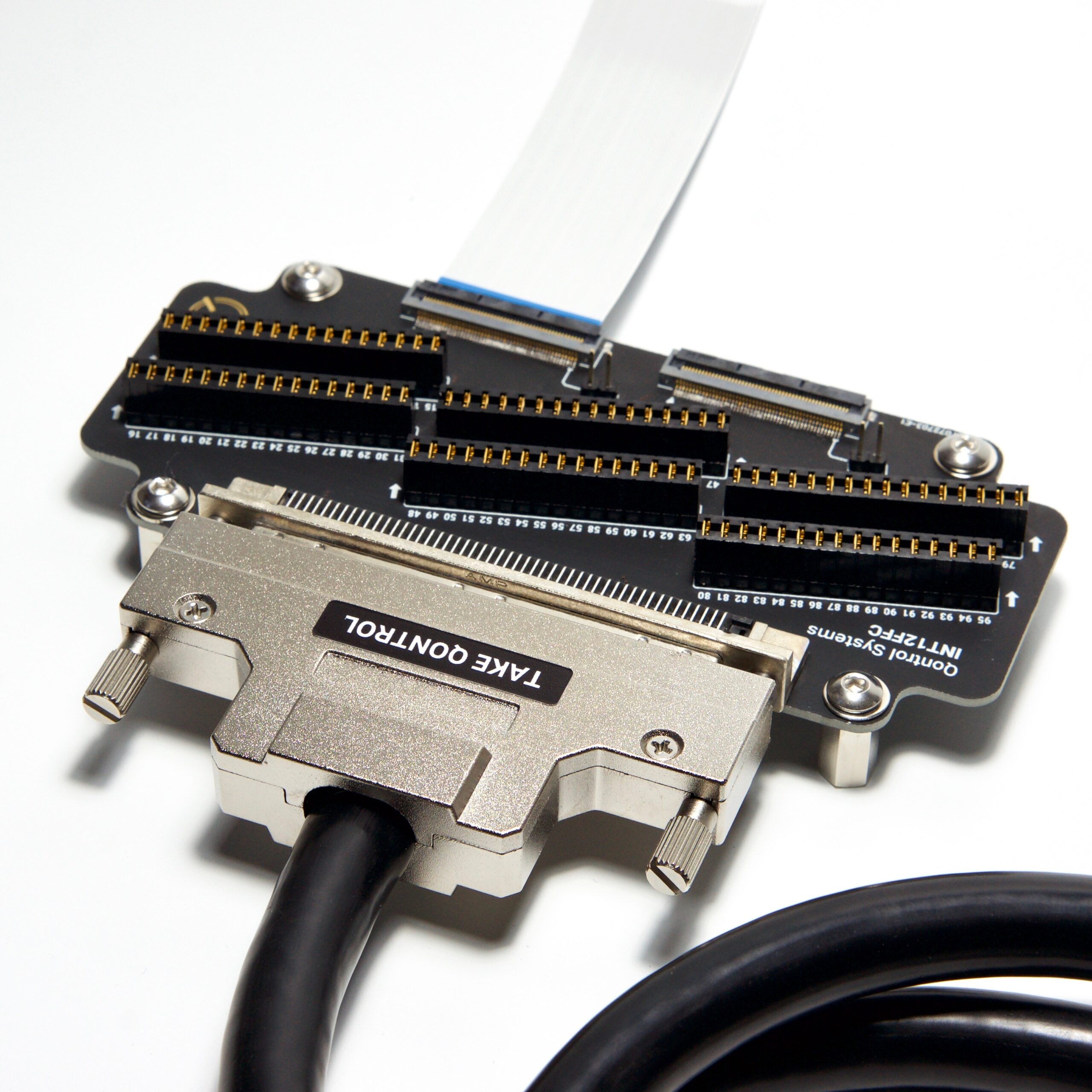
Using the CAB8 and CAB12 without an interposer
By
Josh
•
Jan 10
News
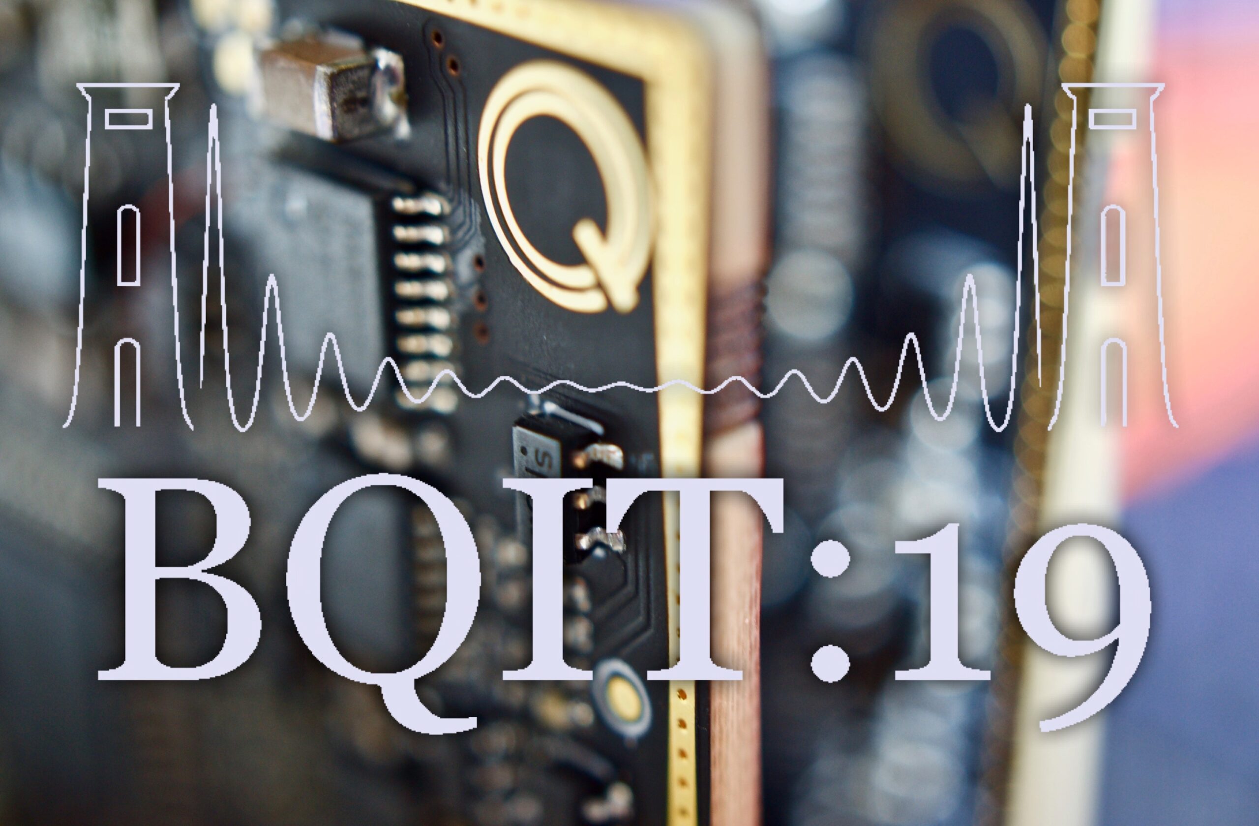
BQIT 2019
By
Liz Martin-Silverstone
•
Apr 14
News
See you at BQIT 2019!
By
Liz Martin-Silverstone
•
Mar 4
Application Notes
How to connect to your chip
By
Josh
•
Apr 14
News
Our new driver, the Q8iv, is coming
By
Liz Martin-Silverstone
•
Mar 17
News
One-stop shop for PIC testing: a new partnership
By
Liz Martin-Silverstone
•
Mar 6
Notes
FAQs now live
By
Liz Martin-Silverstone
•
Mar 2
1
2
Next Page